Welcome to the DSpace Badge Base build docs.
This project builds a base board on which the DSpace Badge kit can be mounted to provide it with a USB serial connection and USB power.
Optionally you can also add components (not included) to:
To use the base kit the DSpace badge kit is fitted with 3 8-pin headers below it and a reset switch, the 3 headers plug into matching sockets on the base board. In it's default configuration the base board contains another AVR CPU which act as as a USB to Serial converter, the USB power is also passed on to power the arduino compatable CPU on the badge.
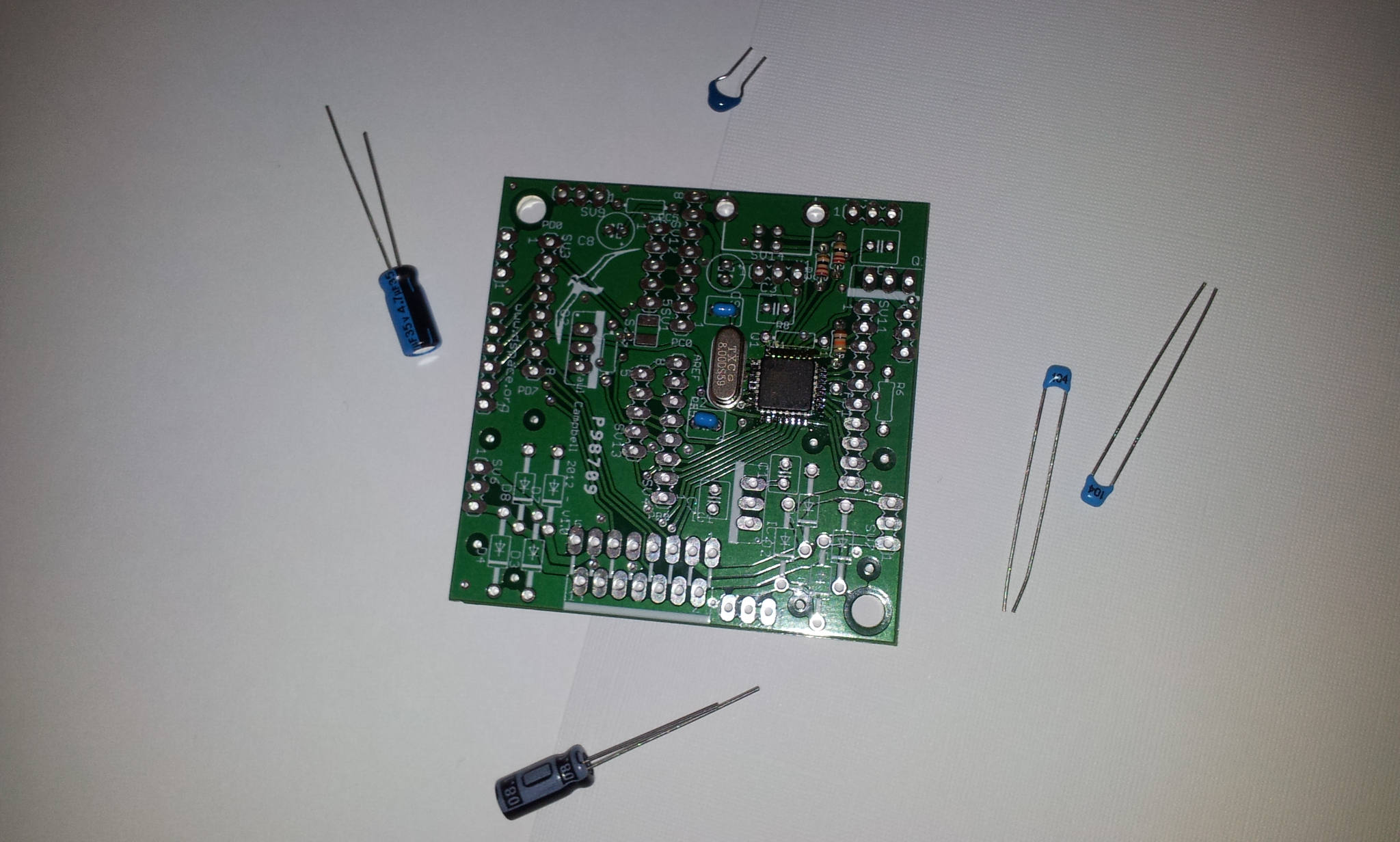
Please check before you start and make sure all the parts are present, if not let us know and we'll hunt them down.
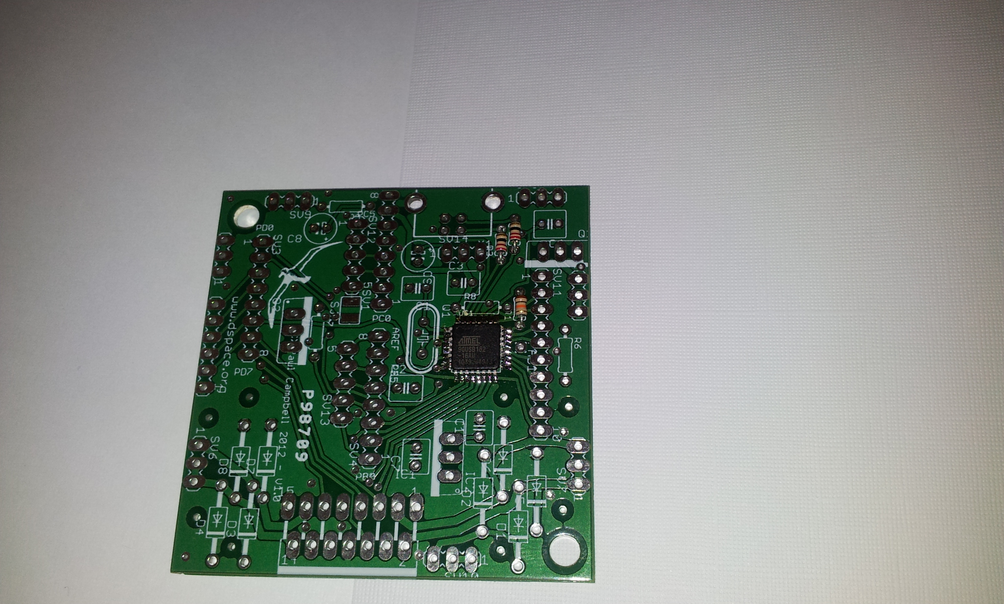
Please also check the soldering of the cpu chip that has been soldered onto your board, make sure that none of the pins around it have been shorted
I usually start with the parts that stick the least above the board then work outwards - this way when you place the board upside down to solder parts they stay in place more easily.
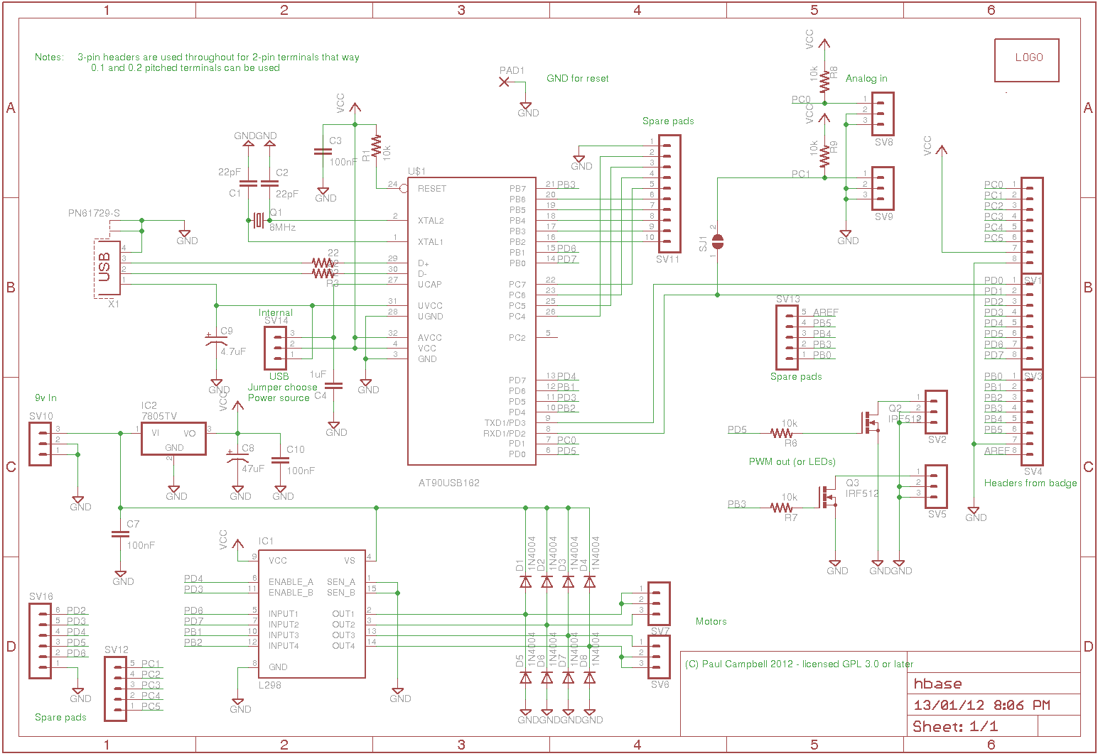
The schematic for what we're building is also available. And if you have a copy of the Eagle CAD program you can look at the layout as well (look in the downloads section)
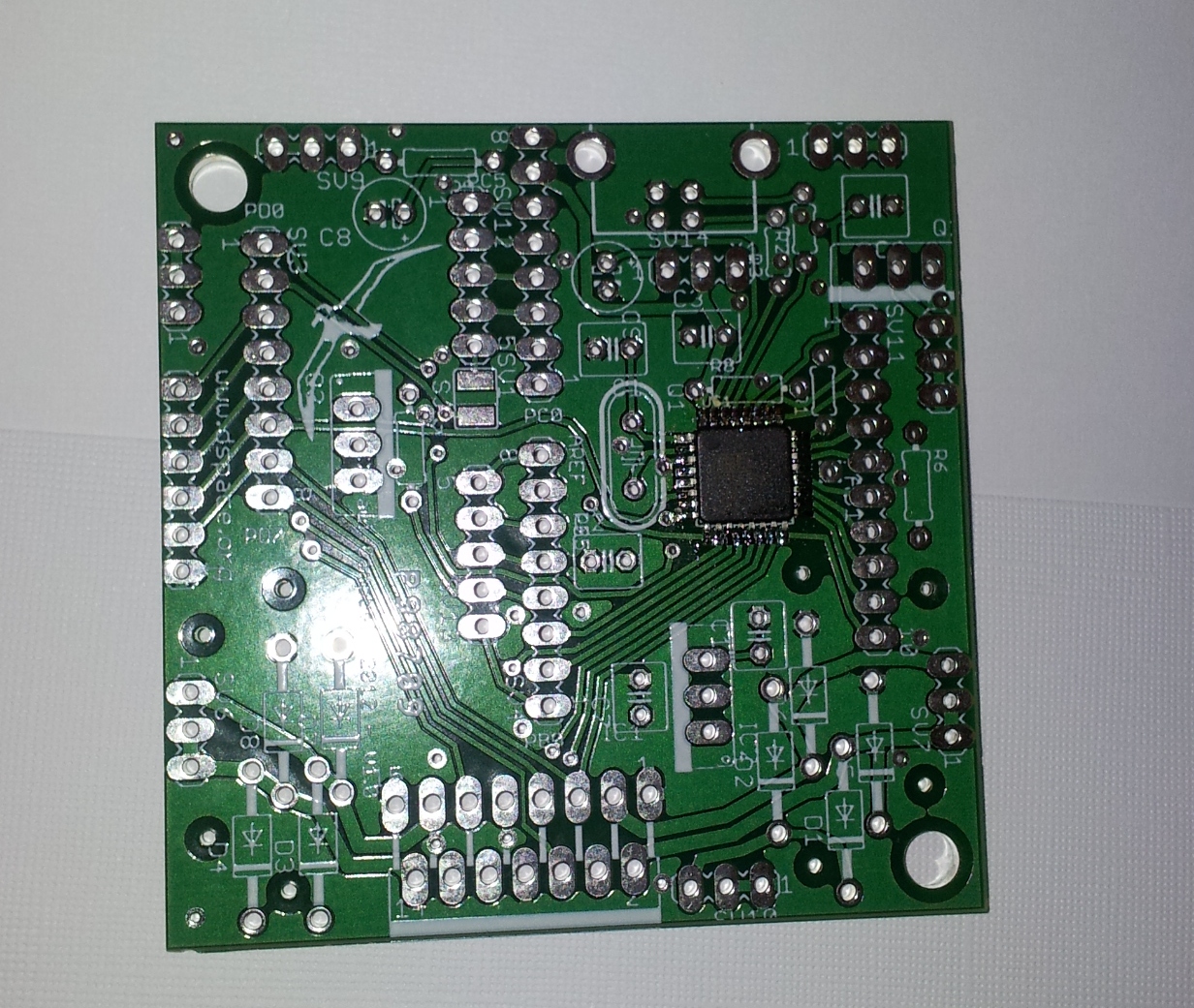
By convention the "top" of this board is where the USB connector is (look for two large holesi at the edge with 4 smaller holes in a square below and between them). The bottom is where the motor controller is (look for a white bar marked at the edge of the board). The "right" side has "R6" clearly marked, and "www.dspace.org" should be on the "left" side. The albatross should be in the top left hand corner
There are 3 resistors, they can go in any way around
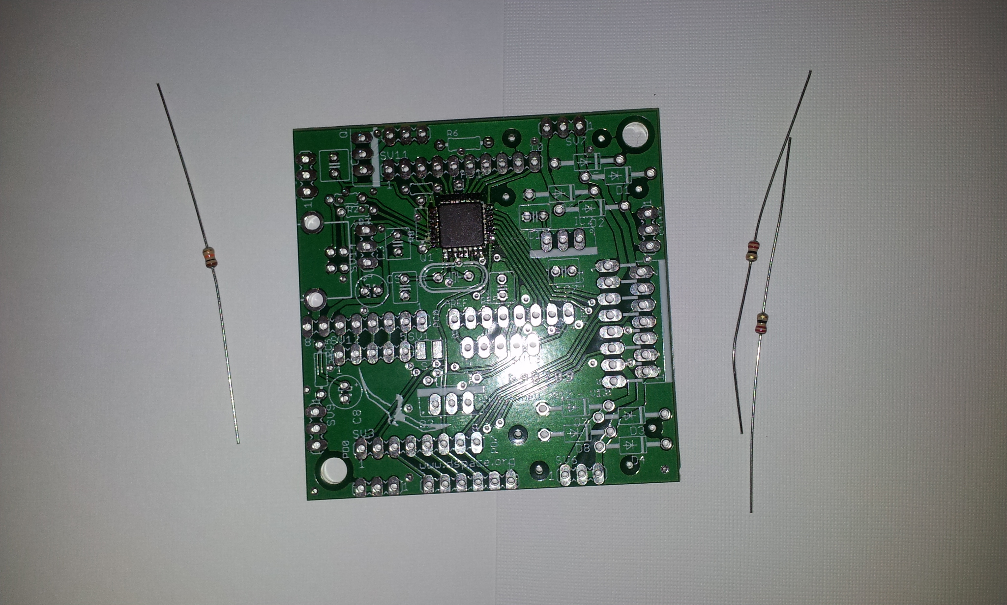
R1 is a 10k resistor (brown-black-orange), it goes to the top right of the CPU. R2 and R3 are 22 ohm resistors (red-red-black) they go to directly above R1 (be carefull they both have a via underneath them, be carefull to get them in the correct holes).
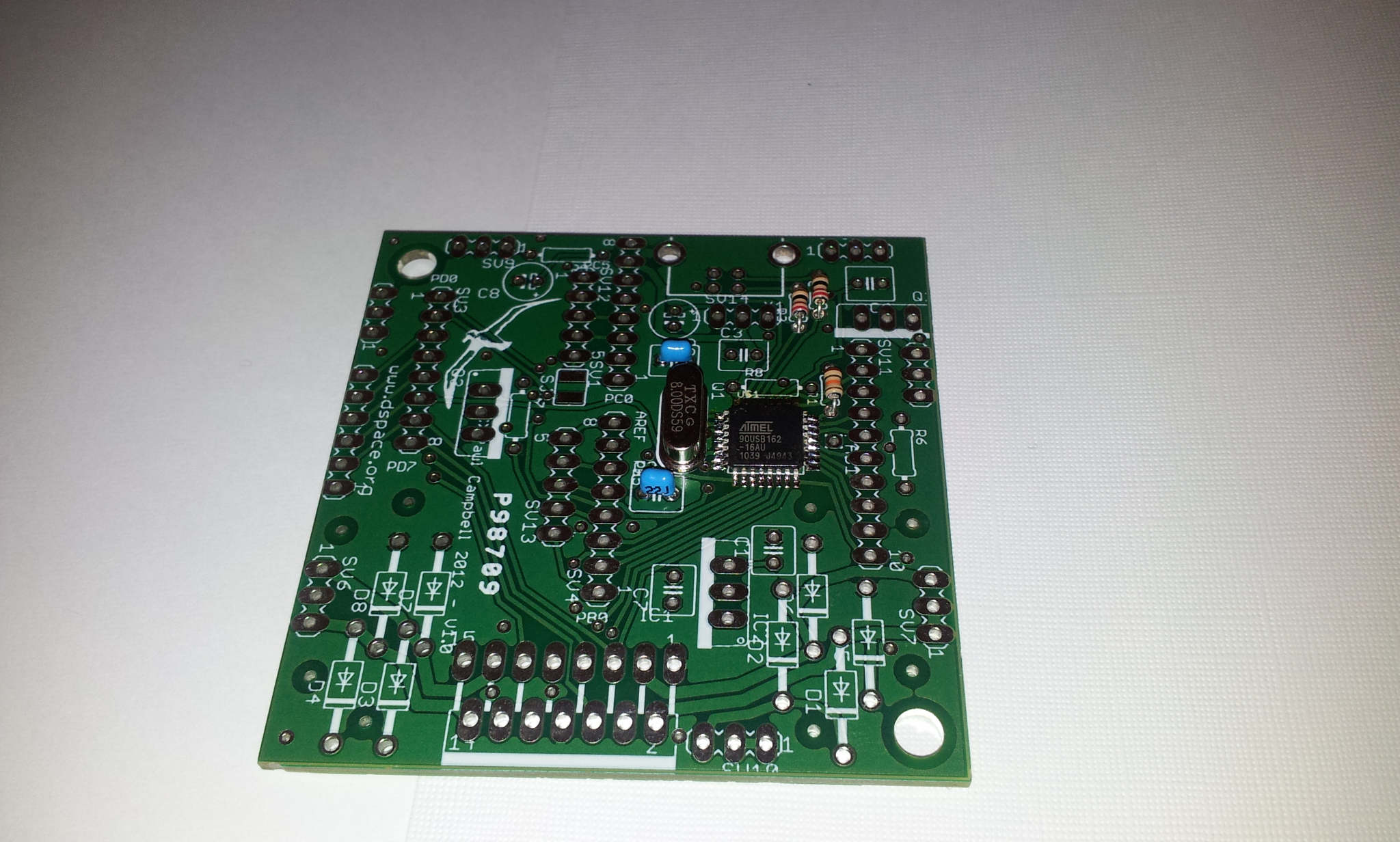
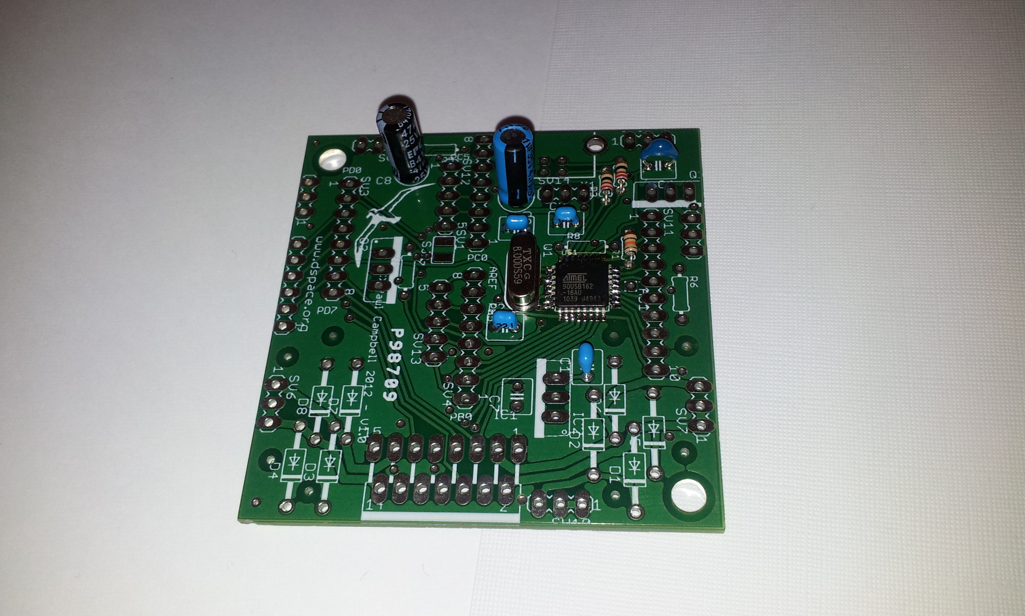
The crystal Q1 is silver coloured, it's two 22pf loading capacitors C1 and C2 have "22" printed on the side
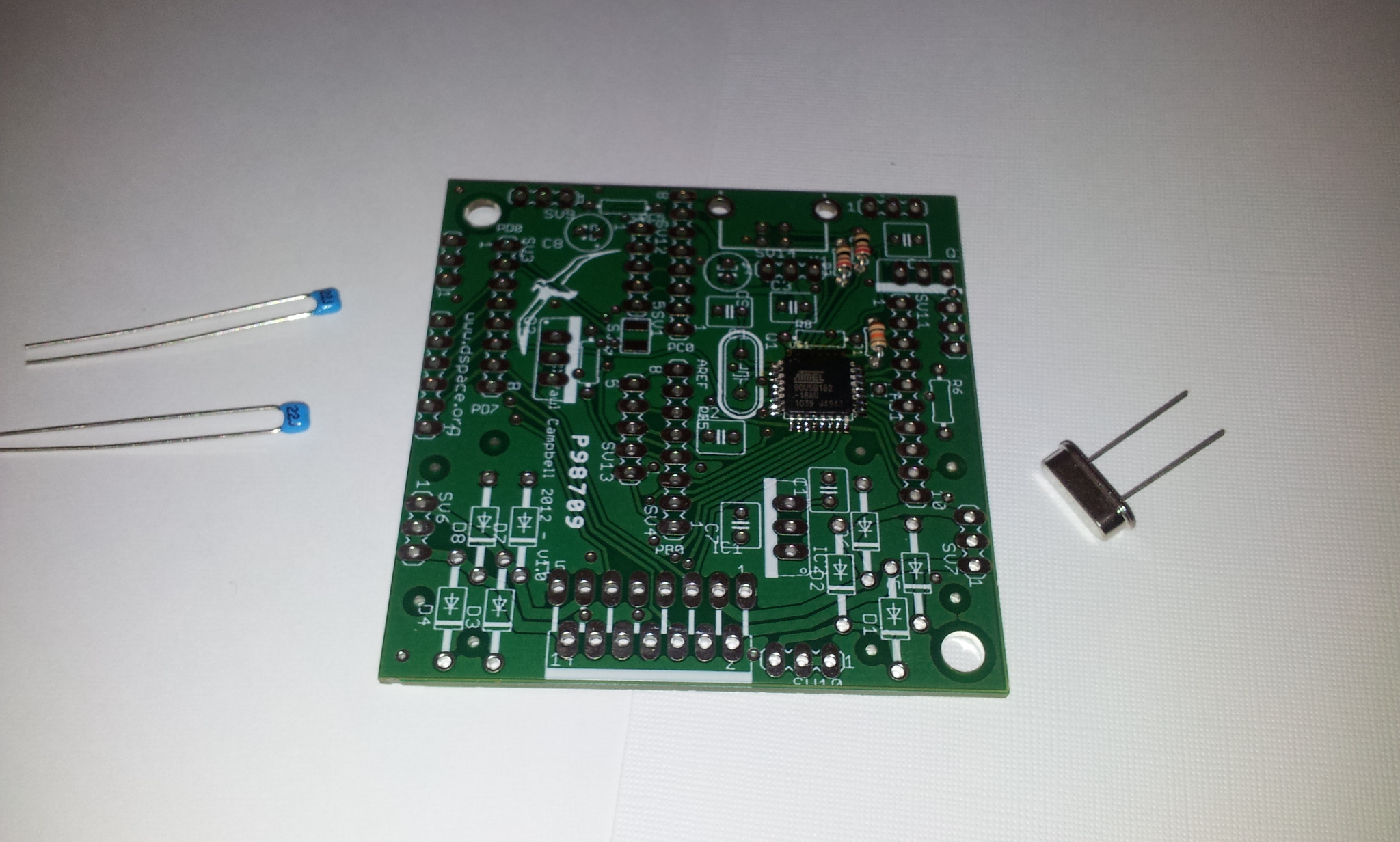
Q1 and the the two capacitors are mounted to the left of the CPU
There are 2 100nF decoupling capacitors (marked "104") - C3 is directly above the CPU, C10 is below it. USB decoupling cap C4 is not marked - it's a darker blue with shorter legs with bends in them it goes in the top right corner of the board. C9 - USB power decoupling cap is a 4.7uF electrolytic - it's located above the crystal - which way around it goes in matters, -ve (the black stripe should go down (face the crystal). Main power decoupling cap C8 is top left on the board, which way around it goes does matter, the -ve side should face left.
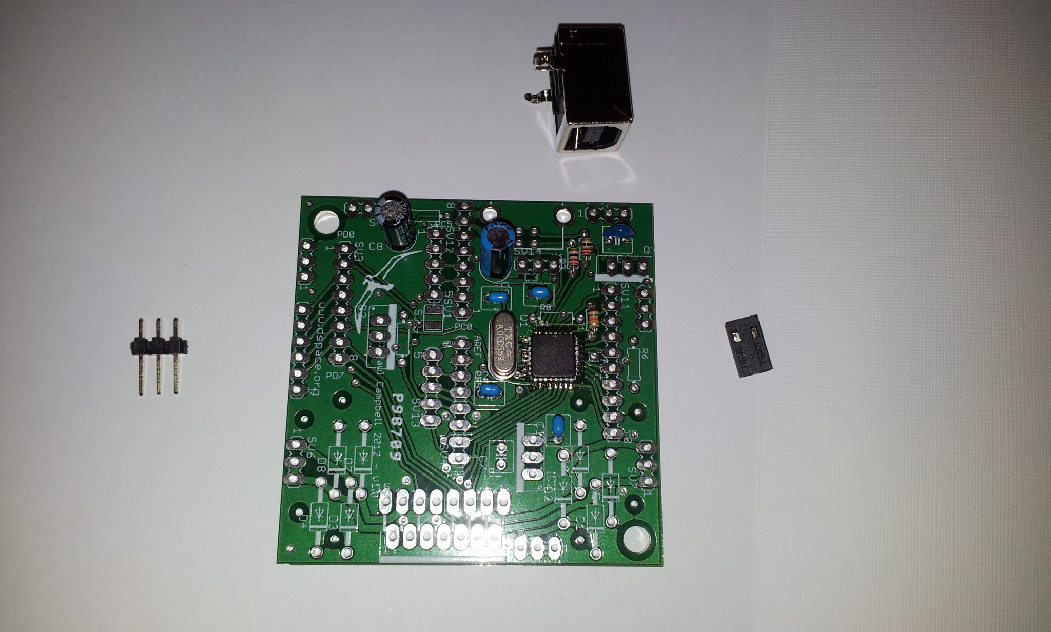
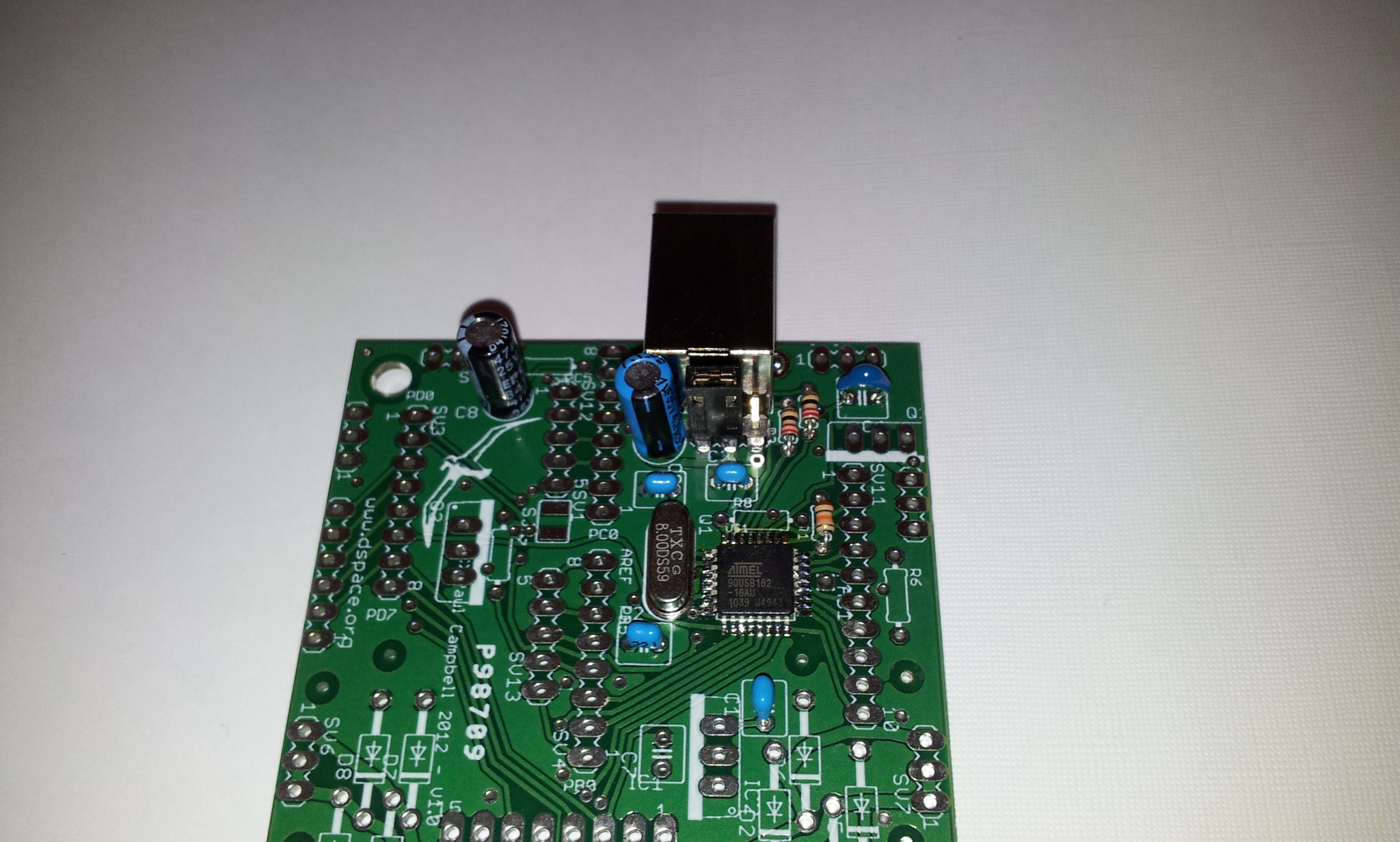
The USB connector goes to the top of the board, the 3 pin power jumper directly below it. Install the jumper to the left (closest to C9) to power the board from USB, remove it if you install a 7805.
SV1, SV3 and SV4 are 8-pin sockets - SV3 and SV1 are mounted either side of the albatross, SV4 is mounted directly below SV1.
Congratulations - you've finished building the base board - now we have to make additions to the badge board so it can be mounted on the base. First of all remove the battery - having the battery in place at the same time as you power things from the base can cause damage. Also unplug any serial cable, you wont need that any more, and again you can cause damage if both are used at the same time
Install the reset switch on top of the board - you only actually need to solder the two upper pins
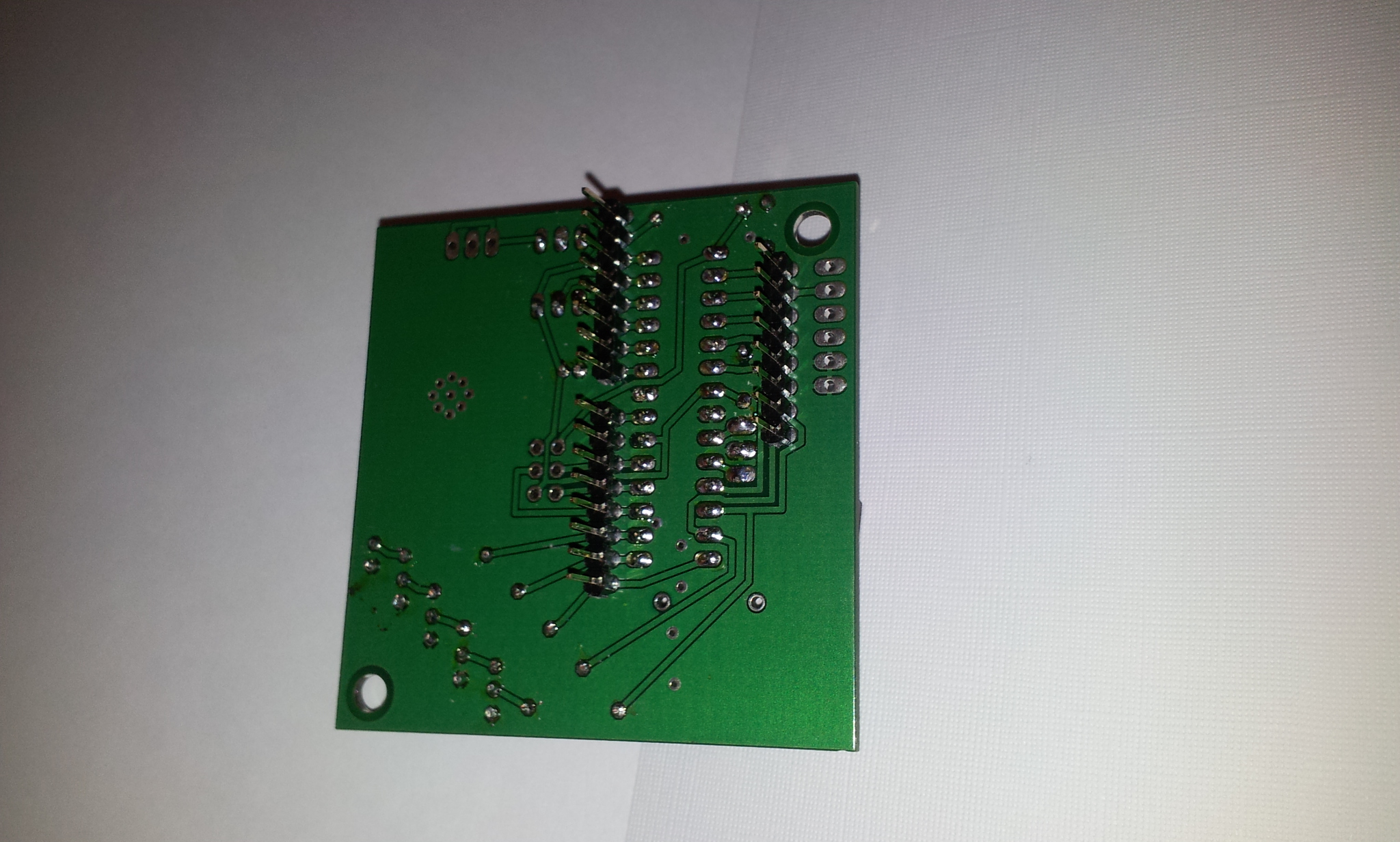
Underneath the badge install the 3 8-pin headers - the goal here is to get the two boards as far away from each other as possible, so you don't want any pins poking up through the board. To align things well use the base board - push the 3 sets of pins into the sockets you installed in the previous section, make sure the long sides of the pins are pointing up.
Push the pins through the badge boards holes then seperate the two boards back as far as possible (use a pair of bolts and some nuts through the corner holes if it helps) tack the ends of each connector underneath then go along and solder the rest of the pins
You're done - go back over your work, look for any shorts or iffy connections
Yes there are lots of unfilled holes on the board - it's designed to be expandable, let's get the basic functionality working first - next step is to load the USB->serial code into the board
Remove the badge board and use a USB cable to plug the base board alone into a computer. On Linux or MacOS if you type "dmesg" you should see something like "usb 2-1.1: new full speed USB device number 8 using ehci_hcd" appear in the log (anyone know what to do on Windows?)
If you don't see that check your work, make sure the crystal is running. Next (linux/OSX) load dfu-programmer and install it on your computer, also down load the the USB->serial firmware and enter the commands:
	sudo dfu-programmer at90usb162 erase
	sudo dfu-programmer at90usb162 flash Benito7g.hex
unplug the board and plug it back in again - you should see something like:
[11874.218385] cdc_acm 2-1.1:1.0: ttyACM0: USB ACM device
[11874.219014] usbcore: registered new interface driver cdc_acm
[11874.219018] cdc_acm: USB Abstract Control Model driver for USB modems and ISDN adapters
appear in your logs - that's your brand new US serial!
Windows users can use Atmel's FLIP utility - someone please sit down with me (Paul) and let me help you get this to work so we can write it up
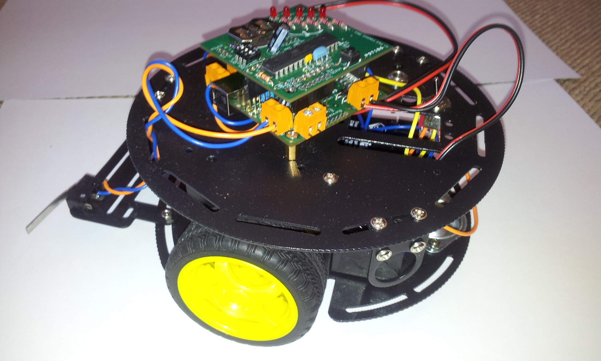
Next step - plug the badge board back on the base - it should light up
Fire up the arduino programming environment, with the board plugged in you should be able to find an extra serial porta available - under linux it will probably be "ttyACM0" (what on other systems? let me know)
Windows users may need a .inf file to get their machine to recognise the USB serial port - here's a windows32 one and a windows64 one - download the appropriate one - open up the Control Panel, go to Syatem and Security, choose System and find the Device Manager - look for a 'Benito' device, right click on it and "Update Driver Software" finally "Browse for Driver Software" and choose the .inf file you downloaded
those of you who are really keen can program the CPU on the base board without the badge board at all - all the pins on the Atmel part used for USB have been provided on pin headers - you can't do this with the Ardiono development system - this is NOT recommended for beginners. There are some quick notes at the end of this page on how to do this.
This section is a work in progress - I'll add more as fast as I can - the base board is a platform for doing many things - all the extra parts you need should be available from local suppliers like Jaycar
The base board is surrounded by 3 pin connections - they're not really 3 pins, insteaed they are 2-pin connectors laid out so that you can use either standard 0.1 inch or 0.2 incg headers or screw terminals (make sure you get the terminals with the fine pitched pins othersie they will be hard to fit. Look at the pads closely if you are soldering wires to them or using 0.1 inch headers to see which 2 of each 3 are shorted together
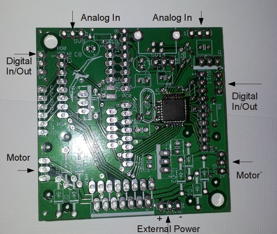
You can use an external power supply anything from about 6v up to 12 will do - WARNING - if you are going to power your board from an external supply, remove the USB power jumper (right below the USB socket), otherwise you may damage your computer
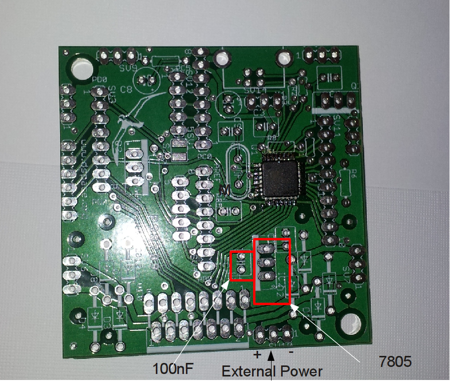
You need two extra components - buy a 7805 5V voltage regulator (TO220 case) and solder it in to the spot shown above - the side with the writing on should face the right, the side that is all flat should face the right (be above the white bar in the silkscreen) - you may have to bend it over slightly so it doesn't hit the badge board above it. Next add a 100nf (0.1nF) capacitor into C7. If you want add an extra electrolytic capacitor (50-100uF) at the input connector
Apply power to the external power connector (location shown above) be careful about polarity - the board should now light up and operate while unplugged from the USB
The pads are present for an L298 dual h-bridge motor controller- this will drive two DC motors in either forwards or backwards directions - make sure you get the 'Multiwatt15' package. If you use this you also need to set up the 'external power supply' above - thye L298 is powered by the incoming power (6-12v, not the regulated 5v) choose a voltage to suit your motors, read the above datasheet link to make sure you don't over drive the L298.
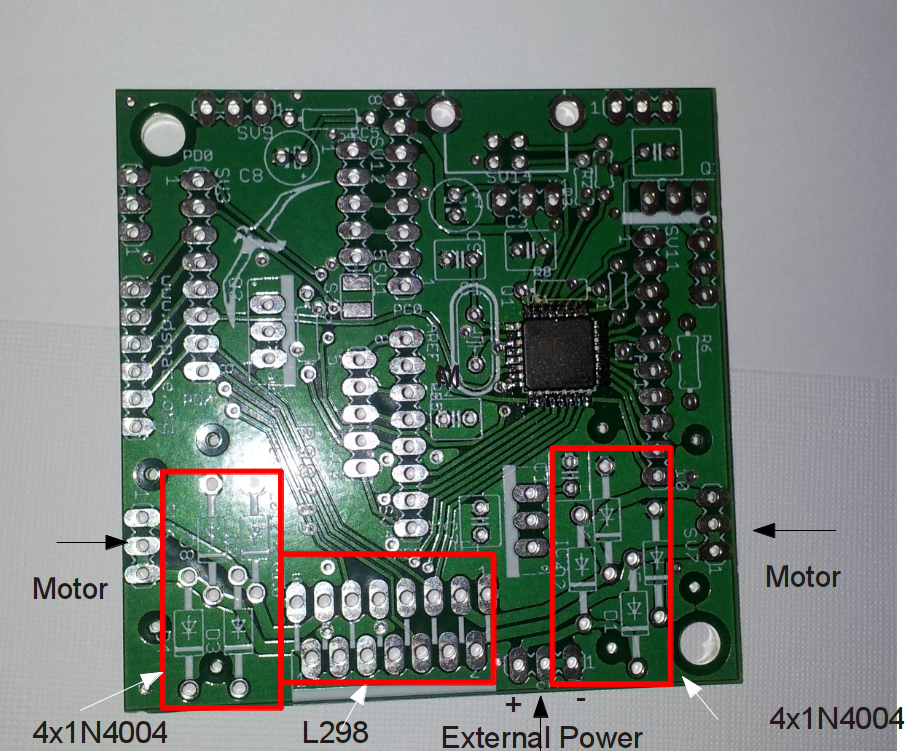
There's only one way to plug this in, bend it slightly so that it extends outside the board and doesn't hit the badge above it, make sure the pins are not shorted. You will also need to install 4 1N4004 protection diodes for each motor (8 total), make sure you put them in the right way around.
Here's some simple sample code showing how to control motors with an L298
As mentioned above the base board is programmable in its own right - it's hard to do and can't be done using the Arduino tools - there's not a lot of SRAM (512 bytes) or ROM (16k) so think small - you could try using the serial source code as a start. Almost all the AT90USB162's pins have been brought out to spare pads on the board should you want to do this
New code can be loaded over USB using dfu-programmer (see the instructions above for loading new code).
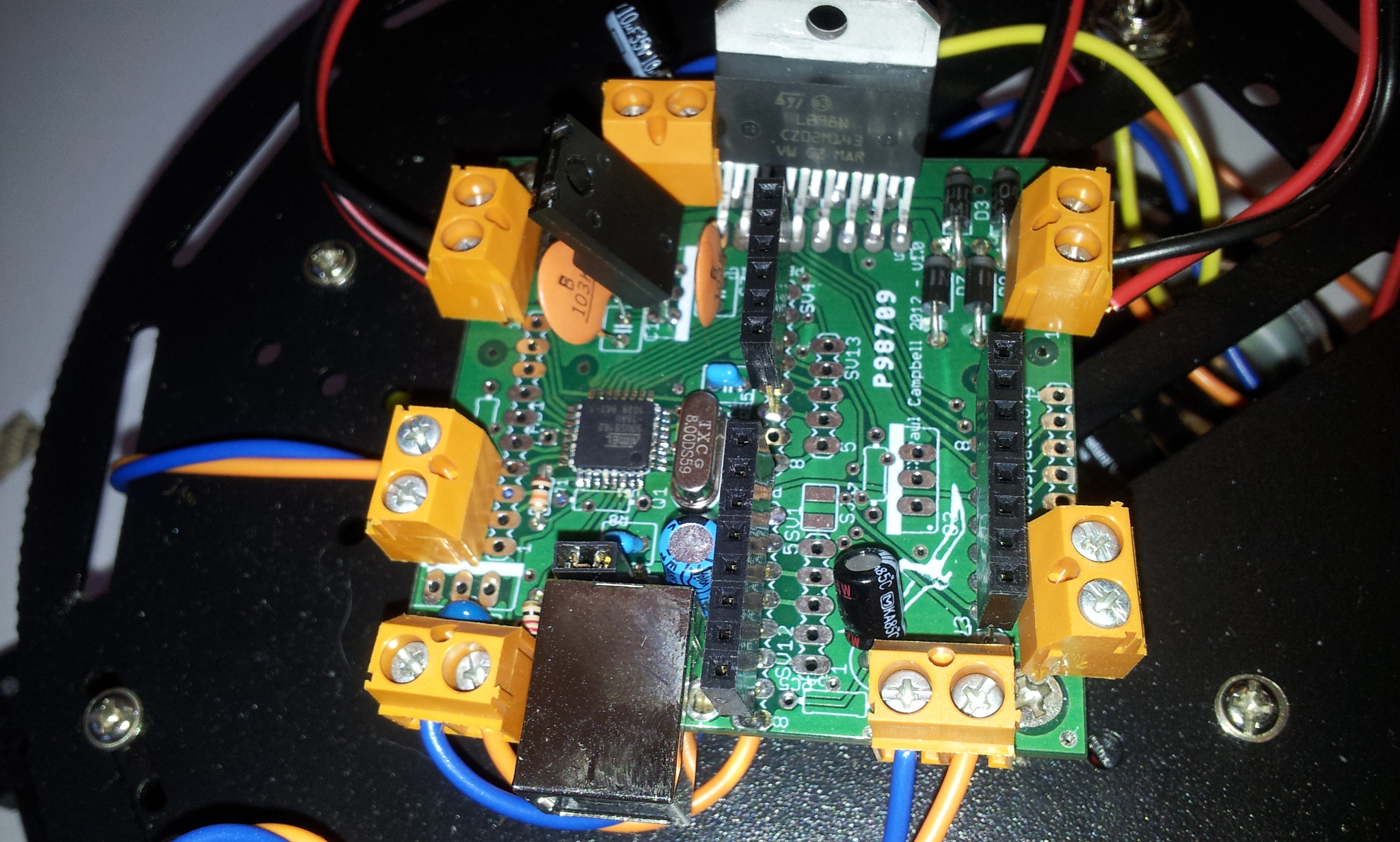
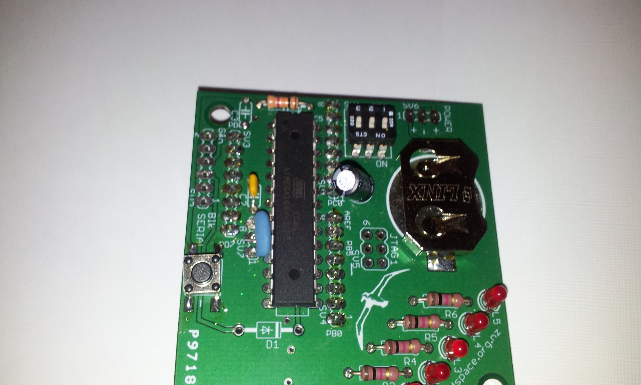
The AT90USB162 chip on the base board has a mode where it will load new code from USB - if you want to reprogram it again you need to be able to put it back into that state - to do this you need to:
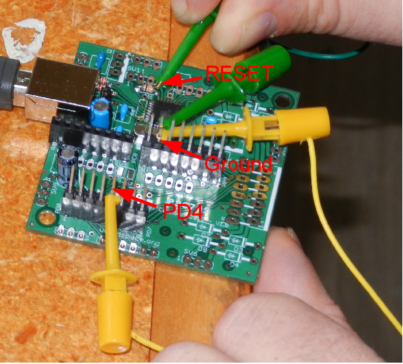
In the above image you can see the yellow clips shorting PD7 (connected thru PD4) to ground and the resistor connected to reset being grounded with the green clip
The USB to serial portion of this design was copied from the excellent Benito project - thanks for sharing!